Blog 3: Arduino
- dylanl21
- Nov 22, 2022
- 7 min read
Updated: Dec 2, 2022
I will first talk about the practical, followed by 4 tasks that will be explained in this page:
1. Input devices:
a. Interface a potentiometer analog input to maker UNO board and measure/show its
signal in serial monitor Arduino IDE.
b. Interface a LDR to maker UNO board and measure/show its signal in serial monitor
Arduino IDE
2. Output devices:
a. Interface 3 LEDs (Red, Yellow, Green) to maker UNO board and program it to perform
something (fade or flash etc)
b. Include the pushbutton on the MakerUno board to start/stop part 2.a. above
For each of the tasks, I will describe:
1. The program/code that I have used and explanation of the code. The code is in writable
format (not an image).
2. The sources/references that I used to write the code/program.
3. The problems I encountered and how I fixed them.
4. The evidence that the code/program worked in the form of video of the executed program/code.
Finally, I will describe:
5. My learning reflection on the overall Arduino programming activities.
Practical
In the practical, Our group was split into 2 smaller groups, a pair and a trio. I was in a group with Darel. You can find his blog here. We were supposed to fold a cardboard unicorn 🦄with wings from a cardboard template given to us.


The end product is assessed based on the criteria below:
1.Perform its main function (flapping)
2.Compact & can easily be moved (no loose pieces)
3.Reliable and durable (doesn’t fail and no parts failing)
4.Aesthetically pleasing
5.Can perform other function
The group challenge has to be completed using our Arduino kits within 150 minutes and each group had 3 minutes to present and demonstrate the end product to the lecturer.

We first started on trying to make the wing flap. I used the same servo code as the Brightspace package as a starting point. Me and Darel then brainstormed on how we could use the servo to flap the wings as it was too bulky to fit into the body. What we ended up doing was coiling a thin metal wire to the wings inside the body and attaching the other end to the servo. This resulted in the wings being pulled and pushed by the servo according to the direction it moved.
I adjusted the code so that the servo would only turn 90 degrees while Darel taped the unicorn on a flat piece of cardboard so it would be more stable. Afterwards, we tried to figure out where we should put the servo. We settled for placing the servo under the unicorn so we had to coil the wire more around the servo and tape the servo down.
Now that we had ensured that we fulfilled the requirement of having the main function and making sure the servo wasn't loose, we moved on to making other functions. Similar to other groups, we wanted to play music. While I was trying to figure out the code, I suggested to Darel that he should connect the wire to the tail so that it would also move.

While he was handling his side of things, I was struggling to find code for music 🎵 online. Most of the codes I found involved other components like a breadboard, a speaker and they used an Arduino Uno which did not have a built-in buzzer like our Maker Uno, which meant that the code was for external buzzers. When I tried using these codes after removing unnecessary parts, it would only result in LEDs flashing but no music. To ensure we still had music if I failed by the end of class, I used the music code from Brightspace and combined it with our current code.
After Darel was done on his end, he started coloring the unicorn with a rainbow style in reference to the character Rainbow Dash from the cartoon My Little Pony to fulfill the aesthetic requirement.

I eventually found a code for music with the tune of 🌟Twinkle Twinkle Little Star 🌟 /
🐑Baa Baa Black Sheep 🐑. When I tried the to test the code after combining the music with the flapping, the wings would flap once and one note would play out of the whole tune and would loop until the tune was done. Apparently, this was because the delay function of the servo would interfere with the music code. I then rearranged the code and added a loop function so that the music would play first, then the wings would flap 10 times. We then presented our unicorn🦄 to our lecturer. Here is our final product and program:
Code/program in writeable format | Explanation of the code |
#include "pitches.h"
// notes in the melody:
int melody[] = {
NOTE_C4, NOTE_G3, NOTE_G3, NOTE_A3, NOTE_G3, 0, NOTE_B3, NOTE_C4
};
// note durations: 4 = quarter note, 8 = eighth note, etc.:
int noteDurations[] = {
4, 8, 8, 4, 4, 4, 4, 4
};
#include <Servo.h>
Servo myservo; // create servo object to control a servo
// twelve servo objects can be created on most boards
int pos = 0; // variable to store the servo position
int piezoPin = 8;
int length = 15;
char notes[] = "ccggaag ffeeddc ggffeed ggffeed ccggaag ffeeddc "; // a space represents a rest
int beats[] = { 1, 1, 1, 1, 1, 1, 2, 1, 1, 1, 1, 1, 1, 2, 4 };
int tempo = 300;
void playTone(int tone, int duration)
{
for (long i = 0; i < duration * 1000L; i += tone * 2)
{
digitalWrite(piezoPin, HIGH);
delayMicroseconds(tone);
digitalWrite(piezoPin, LOW);
delayMicroseconds(tone);
}
}
void playNote(char note, int duration)
{
char names[] = { 'c', 'd', 'e', 'f', 'g', 'a', 'b', 'C' };
int tones[] = { 1915, 1700, 1519, 1432, 1275, 1136, 1014, 956 };
for (int i = 0; i < 8; i++)
{
if (names[i] == note)
{
playTone(tones[i], duration);
}
}
}
void setup() {
myservo.attach(9); // attaches the servo on pin 9 to the servo object
// iterate over the notes of the melody:
pinMode(piezoPin, OUTPUT);
}
void loop() {
{
for (int i = 0; i < length; i++)
{
if (notes[i] == ' ')
{
delay(beats[i] * tempo);
} else
playNote(notes[i], beats[i] * tempo);
delay(tempo / 2);
noTone(8);
}
for (int i=0; i < 10; i++)
{
for (pos = 0; pos <= 90; pos += 1) { // goes from 0 degrees to 90 degrees
// in steps of 1 degree
myservo.write(pos); // tell servo to go to position in variable 'pos'
delay(5); // waits 5ms for the servo to reach the position
}
for (pos = 90; pos >= 0; pos -= 1) { // goes from 90 degrees to 0 degrees
myservo.write(pos); // tell servo to go to position in variable 'pos'
delay(5); // waits 5ms for the servo to reach the position
}
}
}
| #include"pitches.h" - refers to the inclusion of all the pitches in a library so that the code can refer to the library if the code is being called. int melody[] - this is an array where integer information are stored in melody array. int noteDurations[] - this stores information of the note duration #include<Servo.h> - refers that it includes Servo's Library Servo myservo;- this line refers to create a servo object named 'myservo' int pos = 0; - creating an integer variable called pos, and of starting value, 0 int piezoPin = 8; - creating an integer variable called piezoPin, and of starting value, 8 int length = 15; - creating an integer variable called length, and of starting value, 15 char notes[] - stores information of the notes, unlike int [], this stores characters / letters int beats[] - stores information of the beats int tempo = 300; - creating an integer variable called tempo, and of starting value, 300 voidplayTone(int tone, int duration) - section which plays the tone for (long i = 0; i < duration * 1000L; i += tone * 2) - long signifies that the target type will have width of at least 32 bits. Int i is set to 0. If i is less than the duration multiplied by 1000 (L tells the compiler that the number is of type long), i value will become i value + tone multiplied by 2. For this command, it will do the following {} for each new value of i digitalWrite(piezoPin, HIGH); - turns the piezoPin on digitalWrite(piezoPin, LOW); - turns the piezoPin off delayMicroseconds(tone); - delay amount of microseconds where amount is equal to value of tone
voidplayNote(char note, int duration) - section which plays the notes char names[] = { 'c', 'd', 'e', 'f', 'g', 'a', 'b', 'C' }; - stores information of note names int tones[] = { 1915, 1700, 1519, 1432, 1275, 1136, 1014, 956 }; - stores information of tone for (int i = 0; i < 8; i++) - integer i is set to 0. When i lesser than 8, i will increase by 1. For this command, it will do the following {} for each new value of i if (names[i] == note) - if value of names is equal to note value, do the following {} playTone(tones[i], duration); - play tone value and duration value myservo.attach(9); - attaches the servo on pin 9 to the servo object pinMode(piezoPin, OUTPUT); - setting piezoPin as an output for (int i = 0; i < length; i++) - i is equal to 0. When value of i is less than length value, value of i will increase by 1. For this command, it will do the following {} for each new value of i if (notes[i] == ' ') - if value of notes is equal to ASCII value of ' ', do the following {} delay(beats[i] * tempo); - wait for beat value multiplied by tempo else playNote(notes[i], beats[i] * tempo); else play note value and beat value multiplied by tempo delay(tempo / 2); - wait for tempo value divided by 2 noTone(8); - stop playing tones on pin 8 for (int i=0; i < 10; i++) - i value is equal to 0. When i is less than 10, value of i will increase by 1. For this command, it will do the following {} for each new value of i for (pos = 0; pos <= 90; pos += 1) - set pos to 0. When pos is less than 90, value of pos will increase by 1. For this command, do the following {} myservo.write(pos); - It will write the value of pos as and be sent to the servo motor. delay(5); - wait for 5 milleseconds for (pos = 90; pos >= 0; pos -= 1) - set pos to 90. When pos is greater than 0, value of pos will decrease by 1. For this command, do the following {}
|
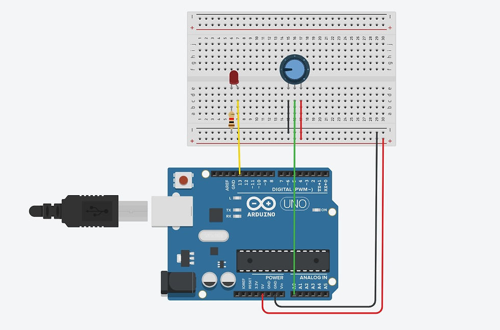
Input devices: Interface a potentiometer analog input to maker UNO board and measure/show its signal in serial monitor Arduino IDE.

1. Below is the code/program I have used and the explanation of the code.
Code/program in writeable format | Explanation of the code |
int sensorValue = 0; void setup() { pinMode(A0, INPUT); pinMode(LED_BUILTIN, OUTPUT); } void loop() { // read the value from the sensor sensorValue = analogRead(A0); // Turn LED on digitalWrite(LED_BUILTIN, HIGH); // Pause the program for <sensorValue> milleseconds delay(sensorValue); // Wait for sensorValue millisecond(s) // Turn LED off digitalWrite(LED_BUILTIN, LOW); // Pause the program for <sensorValue> milleseconds delay(sensorValue); // Wait for sensorValue millisecond(s) } | int sensorValue = 0; - creates an integer variable called sensorValue, and of starting value 0 pinMode(A0, INPUT); - sets analog pin A0 as input pinMode(LED_BUILTIN, OUTPUT); - sets LED at pin 13 as output sensorValue = analogRead(A0); - makes variable sensorValue = A0 input value digitalWrite(LED_BUILTIN, HIGH); - turns on pin 13 LED delay(sensorValue); - wait for sensorValue amount of milleseconds digitalWrite(LED_BUILTIN, LOW); - turns off pin 13 LED The frequency of the LED blinking depends on the resistance of the potentiometer |
2. Below are the hyperlink to the sources/references that I used to write the code/program
Potentiometer Analog Input With Arduino in Tinkercad (Video)
3. Below are the problems I have encountered and how I fixed them.
When I first started the code, I realised my LED was not turned on and quickly figured out that the LED's positive pin and negative pin were in the wrong positions. To solve this, I simply switched the LED pin connections.
The next issue I encountered was my LED being constantly on instead of flashing which made me really confused. I eventually realised that the problem was the red wire connecting the potentiometer was also connected to the negative power rail instead of the positive power rail. Once I moved the red wire to the correct position at the positive power rail, the code worked normally.
4. Below is the short video as the evidence that the code/program work.
Input devices: Interface a LDR to maker UNO board and measure/show its signal in serial monitor Arduino IDE.
1. Below is the code/program I have used and the explanation of the code.
Code/program in writeable format | Explanation of the code |
int light; void setup() { Serial.begin(9600); } void loop() { light=analogRead(A0); Serial.println(light); delay(100); } | int light; - creates an integer variable called light
Serial.begin(9600); - Serial. begin() establishes serial communication between your Arduino board and another device. light=analogRead(A0); - make the value of variable light equal the value read by input A0
Serial.println(light); - displays the value of light
delay(100); - wait for 0.1 seconds
|
2. Below are the hyperlink to the sources/references that I used to write the code/program
LDR with Arduino - Measure Light Intensity using Photoresistor
3. Below are the problems I have encountered and how I fixed them. When I first started the program, I was confused as to why the serial monitor was showing a bunch of ? marks and the serial plotter had no movement. After troubleshooting for a while, I realised the problem was that I did not set the band to the same number as the serial.begin() number.
4. Below is the short video as the evidence that the code/program work.
Output devices: Interface 3 LEDs (Red, Yellow, Green) to maker UNO board and program it to perform something (fade or flash etc)


1. Below is the code/program I have used and the explanation of the code.
Code/program in writeable format | Explanation of the code |
int LEDdelay = 0;
void setup()
{
pinMode(LED_BUILTIN, OUTPUT);
pinMode(12, OUTPUT);
pinMode(11, OUTPUT);
}
void loop()
{
LEDdelay = 400;
digitalWrite(LED_BUILTIN, HIGH);
delay(LEDdelay); // Wait for LEDdelay millisecond(s)
digitalWrite(LED_BUILTIN, LOW);
delay(LEDdelay); // Wait for LEDdelay millisecond(s)
digitalWrite(12, HIGH);
delay(LEDdelay); // Wait for LEDdelay millisecond(s)
digitalWrite(12, LOW);
delay(LEDdelay); // Wait for LEDdelay millisecond(s)
digitalWrite(11, HIGH);
delay(LEDdelay); // Wait for LEDdelay millisecond(s)
digitalWrite(11, LOW);
delay(LEDdelay); // Wait for LEDdelay millisecond(s)
}
| int LEDdelay = 0; - creates an integer variable called LEDdelay, and of starting value 0 pinMode(LED_BUILTIN, OUTPUT); - sets the LED at pin 13 as output pinMode(12, OUTPUT); - sets the LED at pin 12 as output pinMode(11, OUTPUT); - sets the LED at pin 11 as output LEDdelay = 400; - sets the value of LEDdelay as 400 digitalWrite(LED_BUILTIN, HIGH); - turns on the LED at pin 13 [When LED_BUILTIN is replaced by a number less than 13, the pin used will change accordingly to that number] delay(LEDdelay); wait for a specified amount of milleseconds where the amount equals the value of LEDdelay digitalWrite(LED_BUILTIN, LOW); - turns off the LED at pin 13 [When LED_BUILTIN is replaced by a number less than 13, the pin used will change accordingly to that number] |
2. Below are the hyperlink to the sources/references that I used to write the code/program
LEDs & Breadboards With Arduino in Tinkercad
3. Below are the problems I have encountered and how I fixed them. Nil
4. Below is the short video as the evidence that the code/program work.
Output devices: Include push button to start/stop the previous task
1. Below is the code/program I have used and the explanation of the code.
Code/program in writeable format | Explanation of the code |
int LEDdelay = 0;
void setup()
{
//start serial connection
Serial.begin(9600);
//configure pin 2 as an input and enable the internal pull-up resistor
pinMode(2, INPUT_PULLUP);
pinMode(LED_BUILTIN, OUTPUT);
pinMode(12, OUTPUT);
pinMode(11, OUTPUT);
}
void loop()
{
//read the pushbutton value into a variable
int sensorVal = digitalRead(2);
//print out the value of the pushbutton
Serial.println(sensorVal);
if (sensorVal == LOW) {
LEDdelay = 400;
digitalWrite(LED_BUILTIN, HIGH);
delay(LEDdelay); // Wait for LEDdelay millisecond(s)
digitalWrite(LED_BUILTIN, LOW);
delay(LEDdelay); // Wait for LEDdelay millisecond(s)
digitalWrite(12, HIGH);
delay(LEDdelay); // Wait for LEDdelay millisecond(s)
digitalWrite(12, LOW);
delay(LEDdelay); // Wait for LEDdelay millisecond(s)
digitalWrite(11, HIGH);
delay(LEDdelay); // Wait for LEDdelay millisecond(s)
digitalWrite(11, LOW);
delay(LEDdelay); // Wait for LEDdelay millisecond(s)
}
}
| int LEDdelay = 0; - creates an integer variable called LEDdelay, and of starting value 0 Serial.begin(9600); - Serial. begin() establishes serial communication between your Arduino board and another device.
pinMode(2, INPUT_PULLUP); - declares that PIN 2 is an INPUT and enables the internal pull up resistor. So, by default, PIN2 status will always be HIGH pinMode(LED_BUILTIN, OUTPUT); - sets the LED at pin 13 as output pinMode(12, OUTPUT); - sets the LED at pin 12 as output pinMode(11, OUTPUT); - sets the LED at pin 11 as output int sensorVal = digitalRead(2); - It reads the input of PIN2 and writes into a INTEGER variable, sensorVal. Serial.println(sensorVal); It displays the value of sensorVal if it is pressed. if (sensorVal == LOW) - if button is pressed, do the following {} LEDdelay = 400; - sets the value of LEDdelay as 400 digitalWrite(LED_BUILTIN, HIGH); - turns on the LED at pin 13 [When LED_BUILTIN is replaced by a number less than 13, the pin used will change accordingly to that number] delay(LEDdelay); wait for a specified amount of milleseconds where the amount equals the value of LEDdelay digitalWrite(LED_BUILTIN, LOW); - turns off the LED at pin 13 [When LED_BUILTIN is replaced by a number less than 13, the pin used will change accordingly to that number] |
2. Below are the hyperlink to the sources/references that I used to write the code/program
Nil
3. Below are the problems I have encountered and how I fixed them. Nil
4. Below is the short video as the evidence that the code/program work.
Below is my Learning Reflection on the overall Arduino Programming activities.
In the past, I had done coding in primary school and secondary school. In primary school, we were given a textbook on scratch block coding and programmed a car's movements and its sensors, preventing it from crossing black lines. In secondary school, I was in robotics for year one and used the Mindstorms application. It was more complicated than scratch in that there were more components and settings to consider. For example, some motors are more damaged than others and all move at different speeds, so the EV3 Brick (the brain) had to be programmed for different motor speeds. If you wanted to program a car to go straight with 2 motors, you had to program the left and right motor separately and test it until the car was moving straight instead of circling around. In the end, it was still block coding. Although I was excited about using the Arduino kit, I fell sick and then had Covid after so I missed 2 of the Arduino lessons where everyone was doing it in class. Luckily, there was a brightspace package I could follow when I received the Arduino kit from my group members. My prior experience with coding helped me developed a mindset to think logically step by step which helped me during this practical. However, using c++ was a large step from block coding as I did not understand some operators and booleans, meant even with the brightspace package. I already knew beforehand that programmers copy other people's code for the sake of convenience but they still had to understand what they were copying to cut out any unnecessary parts. In my case, the brightspace package had full video guides on what to do and explained the code. I felt that some explanations in the brightspace package were lacking however. For example, clarifying the use of serial.begin(), as the program can clearly function without it so it an additional function that can be used through the serial monitor. The brightspace package simply says that it establishes serial connection between the Arduino board and my device which made me confused. During the practical, I was having great difficulty searching for programs for music for our unicorn. As I had mentioned previously, the programs that I discovered were for the normal Arduino board that did not have a built-in buzzer. While searching, my sinuses were acting up due to a lack of sleep which worsened my condition to do my work. I was also trying to understand most of the programs I found to remove unnecessary bits, only to be confused and disappointed that it didn't work. This reinforced my current belief that programming was extremely difficult. However, I enjoyed doing the post-practical activities, connecting different parts on the breadboard and seeing how they interacted with each other.
Overall, I still feel that this activity was a great learning experience in learning a new skillset. I felt that explaining the code was troublesome but I knew this was to show that we understood what each part of the program does. I know my group will rely on me for the Arduino coding during the CPDD project and I hope I can meet their expectations with my more proficient hands with the Arduino.
Comments