Blog 6: Project Development
- dylanl21
- Feb 18, 2023
- 9 min read
Updated: Feb 20, 2023

In this page, I will:
Briefly describe my team chemical device
Show how the team planned, allocated the tasks, and executed the project.
Document the entire design and build process of the chemical device and include videos, pictures, and screen captures of the processes.
Include “Hero shot” of every milestone of the processes, example the part A that was 3D printed, part B that was laser-cut, electronics components moved/worked according to the program. Hero-shot is taken with the person-in-charge holding/working/making the parts.
Include the name of the person who was in-charge of every part of the project.
Document my individual contribution to this project.
Provide the link to the page of the blog of my teammates.
Describe problems encountered and how the team solved them.
Include all the project design files as downloadable files.
Embed the final prototype design file, i.e., the final fusion360 design file showing the entire prototype.
Type my Learning reflection on the overall project development.
1. Our team Chemical Device
In this section, I will briefly describe my team chemical device.
What it is. What problems will the chemical device solve?
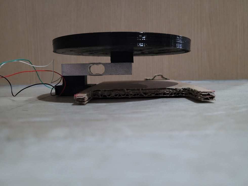
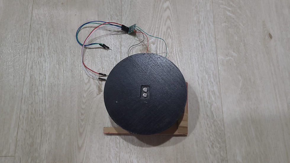
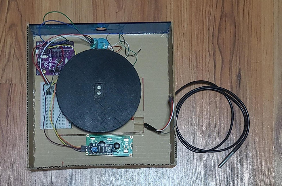
Our chemical device is a tea maker. It is a box consisting of a casing covering a circular plate connected to a load cell, a temperature sensor, an Arduino, a bunch of wires and a breadboard. The load cell measures the weight placed on the plate and with density, is proportionate to volume. The program for the load cell tares when it is reset. The LCD display shows the temperature and volume given by the signals of the electrical parts.
There is also a stand with a continuous servo attached to a wheel on top that acts as a pulley to pull the metal filter from the teapot with a press of a button to lift it up or down and to stop the servo.
The chemical device will try to simplify the process and reduce the steps involved in making tea. The volume and temperature display allows the user to ensure the quality of their tea without bringing out a measuring cup or a food thermometer. The pulley allows the removal of the metal filter safely, while also ensuring that the tea leaves do not steep longer than necessary. As tea leaves come in varieties and they all have different requirements for brewing, the user has to time the heating and control the pulley themselves.

Below is the hand sketch of the chemical device.

This sketch was made before the idea of the stand came about :V

Final Sketch
2. Team Planning, allocation, and execution
In this section, I will list down my team member's name and their respective roles (CEO, CFO, COO, CSO)
Dylan Low, me (CFO)
Darel Suen Ka Chun (CSO)
Long Jingxuan Kerri (CEO)
Kelvin Ang (COO)
Nur Firzanah Binte Roslan (CSO)
I will show the finalized BOM (BILL OF MATERIALS) table.

I will show the finalized Gantt chart (planned and actual) and the tasks allocation for each team member.
3. Design and Build Process
In this section, I will provide documentation of the design and build process.
After seeing the load cell in the components list and reading the description of its use on Cytron Marketplace, I thought that we could use the load cell to show the volume on the LCD Display. I looked up how to use the load cell and drew a rough idea of the base and plate with the load cell in the sketch.
Load Cells A load cell converts a force into an electrical signal that can be measured. The electrical signal changes proportionally to the force applied. There are different types of load cells: strain gauges, pneumatic, and hydraulic. The load cells provided were the strain gauge type.
 Strain gauge load cells are composed of a metal bar with attached strain gauges (under the white glue in the picture above). A strain gauge is an electrical sensor that measures force or strain on an object. The resistance of the strain gauges varies when an external force is applied to an object, which results in a deformation of the object’s shape (in this case, the metal bar). The strain gauge resistance is proportional to the load applied, which allows us to calculate the weight of objects.  Because the changes in strain when weighting objects are so small, we need an amplifier. HX711 Amplifier The load cell provided comes with a HX711 amplifier. The HX711 amplifier is a breakout board that allows you to easily read load cells to measure weight. You wire the load cell wires on one side, and the microcontroller on the other side. The HX711 communicates with the microcontroller using two-wire interface (Clock and Data).  You need to solder header pins on the GND, DT, SCK, and VCC pins to connect to the Arduino which the staff at W3 had already done for us.  |
|---|
I looked up how to use the load cell and drew a rough idea of the base and plate with the load cell in the sketch. I also described and sent references to Firzanah so she could design and 3D print the required objects. The 3D printed objects required holes for screws to go into the load cell to secure the parts together. The holes needed space for the screw head and the longest screws available in W3 that would fit into the load cell would only have a thread height of 2.5 cm. The spacers had to be a certain height due to making space for the screw heads to ensure the 3D prints' structural integrity. These requirements and limitations would influence the design of the prints.
At one point, after thinking about the time constraints of 3D printing. I decided to alter the design of the base and incorporate cardboard. The cardboard that serves as counterweight could also be adjusted in the future by cutting it.
Once the base was finally printed, me and Darel cut up cardboard pieces to hot glue them to the protruding part of the 3D print.


Part 2. Programming of load cell, temperature sensor and LCD (done by ME & Kelvin) These are the links to final programs we used as a basis for our Arduino code.
Load Cell and LCD Display:
Temperature sensor and LCD Display:
Learning that the terminal strips of the breadboard were linked within the same row, we used that knowledge to combine the wiring shown in the links above.


For the load cell program, we deleted the parts which showed the text "WEIGHT SCALE", changed the text "Reading:" into "Volume:", and the unit from kgs to L.
We then slowly brought the temperature sensor code by portions into our program. We deleted the Fahrenheit related pieces of code. This allowed the temperature in degree celsius to fill in the empty space from deleting the "WEIGHT SCALE" text. Lastly, I added a final line of code for the program to write out the text "Temp.:" on the LCD display on the left of the temperature reading. The word "Temperature" was too long. 😳😳

Afterwards was calibrating the load cell for the weight/volume of the program. We placed the Miniso teapot on the plate and opened the program to tare. We then poured a range of volumes of tap water into the kettle so that we could adjust the calibration factor enough for the LCD to show the volume of water inside with sufficient accuracy.
You can find the program at Part 5.

Part 3. Laser cutting acrylic parts (done by Firzanah).
Part 4. Design and build of casing (done by ME & Kelvin).
The casing is a cuboid with space for the LCD screen and a hole for the temperature sensors at the sides and a circular hole at the top for the plate.
After receiving the acrylic parts, we compared them to the space taken up by the electrical components like the breadboard and wires and realised some of the acrylic parts were too small. Trying to reduce the space taken up by the breadboard, I cut out a part of the cardboard counterweight to slide the breadboard into.
I made a square cardboard base 24 cm wide, compared to the 18 cm acrylic top initially planned. I asked Kelvin to help me make the walls of the casing which were 6 cm tall. We used lap joints and hot glue to reduce the seams of cardboard shown. For the back wall, a suitable acrylic piece with a hole was used. For the front wall, a rectangular hole slightly wider than the dimensions [2.5 cm x 7 cm] of the LCD display was cut out. For the lid, I improvised with the smaller acrylic part meant for the top with brass pins.
This design allowed the acrylic piece to be removed.
The Arduino was held down with brass pins while the amplifier was held down with blu tack.


Part 6. Programming the servo (Kelvin)
Part 7. Integration of all parts and electronics (done by Darel)
4. Problems and solutions
In this section I will describe the problems encountered in the design and build process and
how the team solved them.
Part 2 problems and solutions:
We initially used a different program for the temperature sensor which came from another website. When I tested this program initially at home, it worked just fine. However, when we tested the code in W3, the temperature was not being displayed on the LCD. After many minutes, we narrowed down the issue to one of the ground pins of the Arduino not working. After changing ground pins, the program worked again. However, when we tested it another day, it didn't work. We decided to use a different program instead.
When combining the codes, we wanted to use a button to switch the displays instead. When pressing a button, an integer would increase by 1. When the integer was 0, the LCD would display the temperature. When the integer was 1, the LCD would show the volume instead. If the integer was 2 or higher, it would reset to 0. In reality, the LCD would flicker between the 2 displays without a button press. We spent several hours to fix the issue but to no avail. Thus, we decided to use the program for part 2 outlined above.

Other problems and solutions:
We initially 3D printed a cover for the LCD but the print failed. The design of the print also didn't have holes or space for wires to connect to the LCD. We decided to handle the LCD display at a later time as it was a part with lower priority. This resulted in the current casing.

The wiring for the load cell is very fragile. Even if we were careful, the wiring would break off from the amplifier. Thus, we had to get replacements each time and learnt to solder to fix it if possible.
The hole at the back of the casing was meant for the temperature sensor, but because of the fragile wiring of the amplifier, a hole was made on the right side of the box instead.
5. Project Design Files as downloadable files In this section, I will provide all the design files (Fusion360 files, .dxf files, .stl files, arduino programs files) as downloadable files.
6. Below is my Learning Reflection on the overall Project Development.
The process of developing a device requires a systematic approach that involves several steps.
Identifying needs/problems
Identifying requirements of the device
Function analysis
Specifications
Morphological chart
Layout/Concept sketch
Concept evaluation matrix
Theory of inventive problem solving (TRIZ)
Bill of materials (BOM)
Project management
Risk assessment
Making the prototype
Etc.
It is evident that the device development process can be challenging but also rewarding. This list of steps is not comprehensive and is only still a portion of the whole process. The process requires significant time and resources, and it can be overwhelming at times. It also requires collaboration, planning, communication, and teamwork. However, each step is crucial, and if executed correctly, it can lead to the successful creation of a device that can solve a real-world problem. The first half of the steps listed defining what the project should achieve, who the stakeholders are, and what resources are required to accomplish the objectives as it is important to define clear and specific project objectives for the group to aim towards.
The identification of needs or problems is the starting point of the process. Ideally, depending on the device, this step would involve thorough research, surveys, and interviews to understand the problem and define it properly. However, since we are students, the device we are making is commonplace and thus easier to identify the needs and problems through research alone. It is also essential to identify the requirements of the device early on, as this will dictate the design process.
The function analysis helps in identifying the functions that the device should have, while identifying the specifications and creating the morphological chart help to explore different design concepts. Creating a layout and concept sketch is the first physical representation of the concept on paper, while the concept evaluation matrix helps to identify the most feasible design.
TRIZ is a problem-solving methodology that resolves technical contradictions and help generate innovative solutions to complex problems. BOM is essential in managing costs, and project management is critical in organizing resources, setting goals, and monitoring progress.
Risk assessment helps to identify hazards and potential risks, recognising risk controls and develop strategies to mitigate them if required, while making the prototype is the final step in the device development process of our CA. This step helps in testing and refining the design to ensure that it works as intended.
Another important aspect of project development is effective communication. It is essential to have open and transparent communication channels between project team members to ensure that everyone is on the same page and working towards a shared goal. Regular communication and progress updates are also critical to ensure that the project stays on track and any issues are addressed promptly. My experience with the CA has allowed me to realise the lacking communication between me and my group members. This was caused by a mix of factors such as time constraints and other projects scheduled to be completed. Conveying what I want from my group members may also require sketches, which is another extra necessary step for clear communication, but it also increases the workload too. Going forward, I would like to try to improve on my weaknesses in communication.
Overall, reflecting on the device development process, it is evident that the process requires collaboration, creativity, and dedication to achieve success. The process can be challenging at times, but if executed correctly, it can lead to the successful creation of a device that solves real-world problems. It is essential to be patient and stay focused throughout the process, and to learn from any mistakes made to improve the development approach in the future. This experience has also changed my perspective on chemical devices I use in my daily life, allowing me to appreciate them more, knowing the amount of work that goes into them.
Comments